


The cables are mainly used in power stations, mass transit underground passenger systems, airports, petrochemical plants, hotels, hospitals, and high-rise buildings.
Basic design to BS 6004:2012
| Flame Retardance (Single Vertical Wire Test) | EN 60332-1-2 |
300/500V
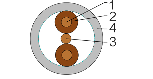
| Conductor | Annealed copper conductor,class 1 (1.0mm² to 2.5mm²) or class 2 (4mm² to 35mm²) according to BS EN 60228. |
| Insulation | PVC Type TI 1 according to BS EN 50363-3. |
| Circuit Protective Conductor (CPC) | Annealed plain copper (class 1 or 2) |
| Position of CPC | Centrally placed between cores in same plane (twin); centrally placed between black and grey cores in same plane(3-core). |
| Outer Sheath | PVC Type 6 according to BS 7655-4.2. |
| Outer Sheath Option | UV resistance,hydrocarbon resistance,oil resistance,anti rodent and anti termite properties can be offered as option. Compliance to fire performance standard (IEC 60332-1,IEC 60332-3,UL 1581,UL 1666 etc) depends on the oxygen index of the PVC compound and the overall cable design. LSPVC can also be provided upon request. |
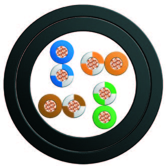
Insulation Colour :
Twin : brown and blue, alternatively, for 2 x 1.0 and 2 x 1.5 cables, brown and brown;
3-core : brown, black (centre core), and grey
Sheath Colour : Grey, other colours can be offered upon request.
| Maximum temperature range during operation (PVC) | 70°C |
| Maximum short circuit temperature (5 Seconds) | 160°C |
| Minimum bending radius | 6 x Overall Diameter |
| Conductor | FLP300-VV-U/R | ||||||
|---|---|---|---|---|---|---|---|
| No. of Cores x Cross Section | Class of Conductor | Nominal Insulation Thickness | Cross-Section Area of CPC | Class of CPC | Nominal Sheath Thickness | Maximum Overall Diameter | Approx. Weight |
| No.xmm² | mm | mm² | mm | mm | kg/km | ||
| 2x1.0 | 1 | 0.6 | 1.0 | 1 | 0.9 | 4.8x8.7 | 68 |
| 2x1.5 | 1 | 0.7 | 1.0 | 1 | 0.9 | 5.3x9.7 | 85 |
| 2x2.5 | 1 | 0.8 | 1.5 | 1 | 1.0 | 6.2x11.7 | 120 |
| 2x4.0 | 2 | 0.8 | 1.5 | 1 | 1.0 | 6.9x13.1 | 175 |
| 2x6.0 | 2 | 0.8 | 2.5 | 1 | 1.1 | 7.8x15.0 | 240 |
| 2x10 | 2 | 1.0 | 4.0 | 2 | 1.2 | 9.5x18.9 | 390 |
| 2x16 | 2 | 1.0 | 6.0 | 2 | 1.3 | 10.8x21.9 | 560 |
| 3x1.0 | 1 | 0.6 | 1.0 | 1 | 0.9 | 4.8x11.4 | 91 |
| 3x1.5 | 1 | 0.7 | 1.0 | 1 | 0.9 | 5.3x12.9 | 115 |
| 3x2.5 | 1 | 0.8 | 1.5 | 1 | 1.0 | 6.2x15.3 | 170 |
| 3x4.0 | 2 | 0.8 | 1.5 | 1 | 1.1 | 7.1x17.9 | 250 |
| 3x6.0 | 2 | 0.8 | 2.5 | 1 | 1.1 | 7.8x20.2 | 340 |
| 3x10 | 2 | 1.0 | 4.0 | 2 | 1.2 | 9.5x25.7 | 540 |
| 3x16 | 2 | 1.0 | 6.0 | 2 | 1.3 | 10.8x29.7 | 790 |
| Conductor Operating Temperature | 70°C |
| Ambient Temperature | 30°C |
| Conductor cross-sectional area | Reference Method 100# (above a plasterboard ceiling covered by thermal insulation not exceeding 100 mm in thickness) | Reference Method 101# (above a plasterboard ceiling covered by thermal insulation exceeding 100 mm in thickness) | Reference Method 102# (in a stud wall with thermal insulation with cable touching the inner wall surface) | Reference Method 103# (in a stud wall with thermal insulation with cable not touching the inner wall surface) | Reference Method C* (clipped direct) | Reference Method A* (enclosed in conduit in an insulated wall) | Voltage Drop (per ampere per meter) |
|---|---|---|---|---|---|---|---|
| 1 | 2 | 3 | 4 | 5 | 6 | 7 | 8 |
| mm² | A | A | A | A | A | A | mV/A/m |
| 1.0 | 13 | 10.5 | 13 | 8.0 | 16 | 11.5 | 44 |
| 1.5 | 16 | 13 | 16 | 10 | 20 | 14.5 | 29 |
| 2.5 | 21 | 17 | 21 | 13.5 | 27 | 20 | 18 |
| 4.0 | 27 | 22 | 27 | 17.5 | 37 | 26 | 11 |
| 6.0 | 34 | 27 | 35 | 23.5 | 47 | 32 | 7.3 |
| 10 | 45 | 36 | 47 | 32 | 64 | 44 | 4.4 |
| 16 | 57 | 46 | 63 | 42.5 | 85 | 57 | 2.8 |
A* For full installation method refer to Table 4A2 (BS 7671-2008) Installation Method 2 but for flat twin and earth cable
C* For full installation method refer to Table 4A2 (BS 7671-2008) Installation Method 20 but for flat twin and earth cable
100# For full installation method refer to Table 4A2 (BS 7671-2008) Installation Method 100
102# For full installation method refer to Table 4A2 (BS 7671-2008) Installation Method 102
103# For full installation method refer to Table 4A2 (BS 7671-2008) Installation Method 103
Wherever practicable, a cable is to be fixed in a position such that it will not be covered with thermal insulation.
Regulation 523.7, BS 5803-5 Appendix C: Avoidance of overheating of electric cables, Building Regulations Approved document B and Thermal insulation: avoiding risks, BR 262, BRE, 2001 refer.