The cables are mainly used in power stations, mass transit underground passenger systems, airports, petrochemical plants, hotels, hospitals, and high-rise buildings.
Basic design adapted to IEC 60502-1
| Flame Retardance (Single Vertical Wire Test) | IEC 60332-1-2 |
600/1000V
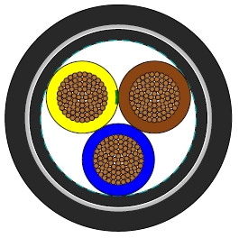
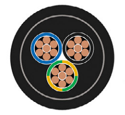
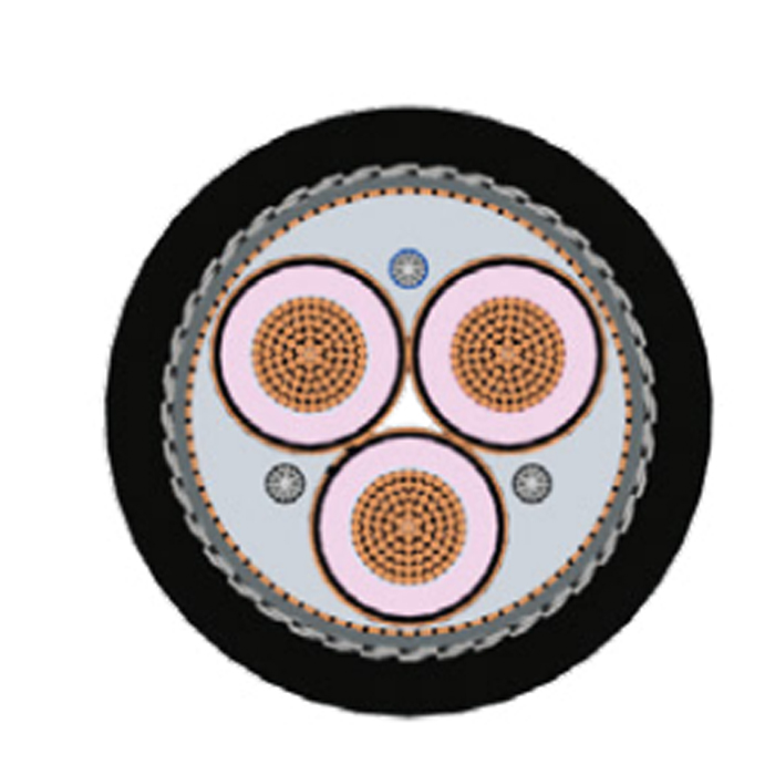
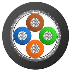
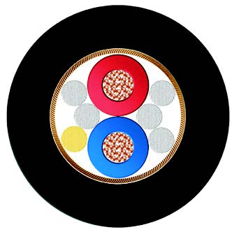
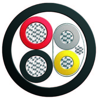
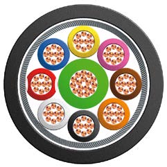
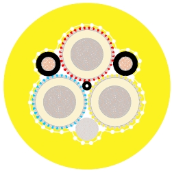
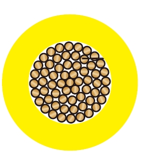
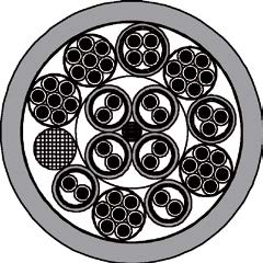
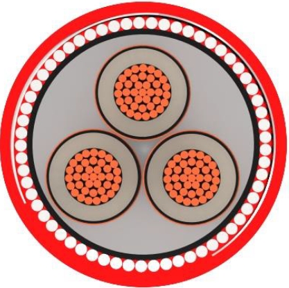
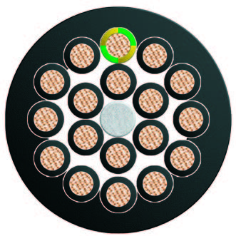
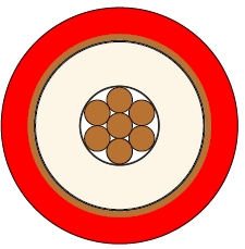
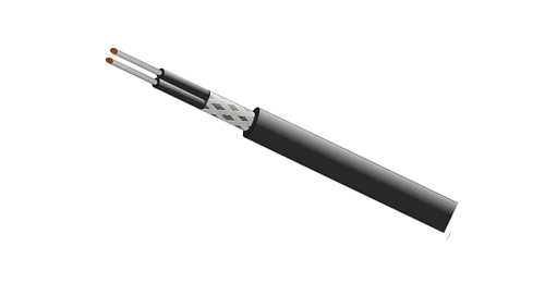
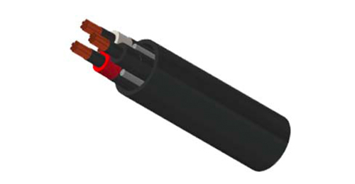
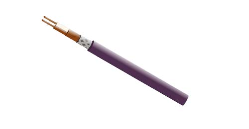
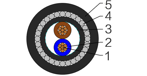
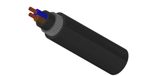
| Conductor | Annealed copper wire, stranded according to IEC 60228 class 2. |
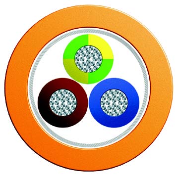
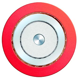
| Insulation | PVC/A according to IEC 60502-1. |
| Inner Covering | Extruded PVC or polymeric compound. |
| Armouring | Galvanized steel wire |
| Outer Sheath | Extruded PVC Type ST1/ST2 according to IEC 60502-1. |
| Outer Sheath Option | UV resistance, hydrocarbon resistance, oil resistance, anti rodent and anti termite properties can be offered as option. Compliance to fire performance standard (IEC 60332-1, IEC 60332-3, UL 1581, UL 1666 etc) depends on the oxygen index of the PVC compound and the overall cable design. LSPVC can also be provided upon request. |
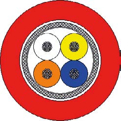
| Insulation Colour | Two-core: Brown, blue Three-core: Brown, black, grey Four-core: Blue, brown, black, grey Five-core: Green-and-yellow, blue, brown, black, grey Other colours can be offered upon request. |
| Sheath Colour | Black, other colours can be offered upon request. |
| Maximum temperature range during operation (PVC) | 70°C |
| Maximum short circuit temperature (5 Seconds) | 160°C(≤300 mm²); 140°C(>300 mm²) |
| Minimum bending radius | |
| Circular copper conductors | 6 x Overall Diameter |
| Shaped copper conductors | 8 x Overall Diameter |
| Conductor | FLP600-VVMV-R | |||||||
|---|---|---|---|---|---|---|---|---|
| No. of Cores x Cross Section | Class of Conductor | Nominal Insulation Thickness | Nominal Inner Covering Thickness | Armour Wire Diameter | Nominal Sheath Thickness | Nominal Overall Diameter | Approx. Weight | |
| No.xmm2 | mm | mm | mm | mm | mm | kg/km | ||
| 2 Cores | ||||||||
| 2x2.5 | 2 | 0.8 | 1.0 | 0.8 | 1.8 | 14.0 | 380 | |
| 2x4.0 | 2 | 1.0 | 1.0 | 1.25 | 1.8 | 16.7 | 604 | |
| 2x6.0 | 2 | 1.0 | 1.0 | 1.25 | 1.8 | 17.7 | 689 | |
| 2x10 | 2 | 1.0 | 1.0 | 1.25 | 1.8 | 19.3 | 841 | |
| 2x16 | 2 | 1.0 | 1.0 | 1.25 | 1.8 | 21.1 | 1037 | |
| 2x25 | 2 | 1.2 | 1.0 | 1.6 | 1.8 | 24.8 | 1513 | |
| 2x35 | 2 | 1.2 | 1.0 | 1.6 | 1.8 | 27.0 | 1843 | |
| 2x50 | 2 | 1.4 | 1.0 | 1.6 | 1.9 | 30.7 | 2356 | |
| 2x70 | 2 | 1.4 | 1.0 | 2.0 | 2.1 | 34.5 | 3179 | |
| 2x95 | 2 | 1.6 | 1.2 | 2.0 | 2.2 | 39.2 | 4042 | |
| 2x120 | 2 | 1.6 | 1.2 | 2.0 | 2.3 | 42.2 | 4764 | |
| 2x150 | 2 | 1.8 | 1.2 | 2.5 | 2.5 | 47.2 | 6095 | |
| 2x185 | 2 | 2.0 | 1.4 | 2.5 | 2.6 | 51.6 | 7207 | |
| 2x240 | 2 | 2.2 | 1.4 | 2.5 | 2.8 | 57.2 | 8861 | |
| 2x300 | 2 | 2.4 | 1.6 | 2.5 | 3.0 | 62.8 | 10608 | |
| 2x400 | 2 | 2.6 | 1.6 | 2.5 | 3.2 | 70.3 | 13385 | |
| 3 Cores | ||||||||
| 3x2.5 | 2 | 0.8 | 1.0 | 0.8 | 1.8 | 14.5 | 432 | |
| 3x4.0 | 2 | 1.0 | 1.0 | 1.25 | 1.8 | 17.4 | 689 | |
| 3x6.0 | 2 | 1.0 | 1.0 | 1.25 | 1.8 | 18.4 | 800 | |
| 3x10 | 2 | 1.0 | 1.0 | 1.25 | 1.8 | 20.2 | 1001 | |
| 3x16 | 2 | 1.0 | 1.0 | 1.6 | 1.8 | 22.8 | 1405 | |
| 3x25 | 2 | 1.2 | 1.0 | 1.6 | 1.8 | 26.0 | 1860 | |
| 3x35 | 2 | 1.2 | 1.0 | 1.6 | 1.9 | 28.5 | 2325 | |
| 3x50 | 2 | 1.4 | 1.0 | 2.0 | 2.0 | 33.3 | 3266 | |
| 3x70 | 2 | 1.4 | 1.2 | 2.0 | 2.1 | 37.0 | 4108 | |
| 3x95 | 2 | 1.6 | 1.2 | 2.0 | 2.3 | 41.6 | 5245 | |
| 3x120 | 2 | 1.6 | 1.2 | 2.5 | 2.4 | 45.9 | 6677 | |
| 3x150 | 2 | 1.8 | 1.4 | 2.5 | 2.6 | 50.4 | 8016 | |
| 3x185 | 2 | 2.0 | 1.4 | 2.5 | 2.7 | 54.8 | 9466 | |
| 3x240 | 2 | 2.2 | 1.5 | 2.5 | 2.9 | 61.2 | 11805 | |
| 3x300 | 2 | 2.4 | 1.6 | 2.5 | 3.1 | 66.8 | 14181 | |
| 3x400 | 2 | 2.8 | 1.6 | 3.15 | 3.4 | 76.7 | 19235 | |
| 3x500 | 2 | 2.8 | 1.8 | 3.15 | 3.7 | 83.6 | 23011 | |
| 3 Cores+1 Earth Conductor | ||||||||
| 3x10/6 | 2 | 1.0 | 1.0 | 1.0 | 1.25 | 1.8 | 21.9 | 1140 |
| 3x16/10 | 2 | 1.0 | 1.0 | 1.0 | 1.6 | 1.8 | 24.2 | 1633 |
| 3x25/16 | 2 | 1.2 | 1.0 | 1.0 | 1.6 | 1.8 | 27.9 | 2145 |
| 3x35/16 | 2 | 1.2 | 1.0 | 1.0 | 1.6 | 1.9 | 30.8 | 2659 |
| 3x50/25 | 2 | 1.4 | 1.2 | 1.0 | 2.0 | 2.0 | 36.4 | 3739 |
| 3x70/35 | 2 | 1.4 | 1.2 | 1.2 | 2.0 | 2.1 | 40.1 | 4720 |
| 3x95/50 | 2 | 1.6 | 1.4 | 1.2 | 2.5 | 2.3 | 46.3 | 6398 |
| 3x120/70 | 2 | 1.6 | 1.4 | 1.4 | 2.5 | 2.4 | 50.3 | 7746 |
| 3x150/70 | 2 | 1.8 | 1.4 | 1.4 | 2.5 | 2.6 | 55.0 | 9128 |
| 3x185/95 | 2 | 2.0 | 1.6 | 1.4 | 2.5 | 2.7 | 60.3 | 10916 |
| 3x240/120 | 2 | 2.2 | 1.6 | 1.6 | 2.5 | 2.9 | 67.0 | 13713 |
| 3x300/150 | 2 | 2.4 | 1.8 | 1.6 | 3.15 | 3.1 | 74.6 | 17403 |
| 3x400/185 | 2 | 2.6 | 2.0 | 1.8 | 3.15 | 3.4 | 84.1 | 20704 |
| 3x500/240 | 2 | 2.8 | 2.2 | 2.0 | 3.15 | 3.7 | 91.8 | 25817 |
| 4 Cores | ||||||||
| 4x4.0 | 2 | 1.0 | 1.0 | 1.25 | 1.8 | 18.5 | 792 | |
| 4x6.0 | 2 | 1.0 | 1.0 | 1.25 | 1.8 | 19.7 | 931 | |
| 4x10 | 2 | 1.0 | 1.0 | 1.25 | 1.8 | 22.3 | 1185 | |
| 4x16 | 2 | 1.0 | 1.0 | 1.6 | 1.8 | 24.5 | 1672 | |
| 4x25 | 2 | 1.2 | 1.0 | 1.6 | 1.9 | 28.2 | 2260 | |
| 4x35 | 2 | 1.2 | 1.0 | 1.6 | 2.0 | 31.1 | 2854 | |
| 4x50 | 2 | 1.4 | 1.0 | 2.0 | 2.1 | 36.7 | 4013 | |
| 4x70 | 2 | 1.4 | 1.2 | 2.0 | 2.3 | 40.4 | 5104 | |
| 4x95 | 2 | 1.6 | 1.2 | 2.5 | 2.5 | 46.6 | 6996 | |
| 4x120 | 2 | 1.6 | 1.4 | 2.5 | 2.6 | 50.6 | 8400 | |
| 4x150 | 2 | 1.8 | 1.4 | 2.5 | 2.7 | 55.3 | 10008 | |
| 4x185 | 2 | 2.0 | 1.4 | 2.5 | 2.9 | 60.6 | 11906 | |
| 4x240 | 2 | 2.2 | 1.6 | 2.5 | 3.1 | 67.3 | 14963 | |
| 4x300 | 2 | 2.4 | 1.6 | 3.15 | 3.4 | 74.9 | 18944 | |
| 4x400 | 2 | 2.6 | 1.8 | 3.15 | 3.7 | 84.4 | 24304 | |
| 4x500 | 2 | 2.8 | 2.0 | 3.15 | 3.9 | 92.1 | 29351 | |
Note: Other conductor sizes & core confi gurations are available upon request.
| Conductor Operating Temperature | 70°C |
| Ambient Temperature | 30°C |
| Conductor crosssectional area | Reference Method C (clipped direct) | Reference Method E (in free air or on a perforated cable tray, horizontal or vertical) | Reference Method D (direct in in groud or in ducting in groud. in or around buildings) | |||
|---|---|---|---|---|---|---|
| 1 two-core cable, single-phase a.c. or d.c. | 1 three-or four core cable, three-phase a.c. | 1 two-core cable, singlephase a.c. or d.c. | 1 three-or four core cable, three-phase a.c. | 1 two-core cable, single-phase a.c. or d.c. | 1 three-or four core cable, threephase a.c. | |
| 1 | 2 | 3 | 4 | 5 | 6 | 7 |
| mm2 | A | A | A | A | A | A |
| 1.5 | 21 | 18 | 22 | 19 | 22 | 18 |
| 2.5 | 28 | 25 | 31 | 26 | 29 | 24 |
| 4.0 | 38 | 33 | 41 | 35 | 37 | 30 |
| 6.0 | 49 | 42 | 53 | 45 | 46 | 38 |
| 10 | 67 | 58 | 72 | 62 | 60 | 50 |
| 16 | 89 | 77 | 97 | 83 | 78 | 64 |
| 25 | 118 | 102 | 128 | 110 | 99 | 82 |
| 35 | 145 | 125 | 157 | 135 | 119 | 98 |
| 50 | 175 | 151 | 190 | 163 | 140 | 116 |
| 70 | 222 | 192 | 241 | 207 | 173 | 143 |
| 95 | 269 | 231 | 291 | 251 | 204 | 169 |
| 120 | 310 | 267 | 336 | 290 | 231 | 192 |
| 150 | 356 | 306 | 386 | 332 | 261 | 217 |
| 185 | 405 | 348 | 439 | 378 | 292 | 243 |
| 240 | 476 | 409 | 516 | 445 | 336 | 280 |
| 300 | 547 | 469 | 592 | 510 | 379 | 316 |
| 400 | 621 | 540 | 683 | 590 | - | - |
| Nominal Cross Section Area | Two-core cables d.c. | Two-core cable, single-phase a.c. | Three- or four-core cable, three-phase a.c. | ||||
|---|---|---|---|---|---|---|---|
| 1 | 2 | 3 | 4 | ||||
| mm2 | mV/A/m | mV/A/m | mV/A/m | ||||
| 1.5 | 29 | 29 | 25 | ||||
| 2.5 | 18 | 18 | 15 | ||||
| 4.0 | 11 | 11 | 9.5 | ||||
| 6.0 | 7.3 | 7.3 | 6.4 | ||||
| 10 | 4.4 | 4.4 | 3.8 | ||||
| 16 | 2.8 | 2.8 | 2.4 | ||||
| r | x | z | r | x | z | ||
| 25 | 1.75 | 1.75 | 0.170 | 1.75 | 1.50 | 0.145 | 1.50 |
| 35 | 1.25 | 1.25 | 0.165 | 1.25 | 1.10 | 0.145 | 1.10 |
| 50 | 0.93 | 0.93 | 0.165 | 0.94 | 0.80 | 0.140 | 0.81 |
| 70 | 0.63 | 0.63 | 0.160 | 0.65 | 0.55 | 0.140 | 0.57 |
| 95 | 0.46 | 0.47 | 0.155 | 0.50 | 0.41 | 0.135 | 0.43 |
| 120 | 0.36 | 0.38 | 0.155 | 0.41 | 0.33 | 0.135 | 0.35 |
| 150 | 0.29 | 0.30 | 0.155 | 0.34 | 0.26 | 0.130 | 0.29 |
| 185 | 0.23 | 0.25 | 0.150 | 0.29 | 0.21 | 0.130 | 0.25 |
| 240 | 0.180 | 0.190 | 0.150 | 0.24 | 0.165 | 0.130 | 0.21 |
| 300 | 0.145 | 0.155 | 0.145 | 0.21 | 0.135 | 0.130 | 0.185 |
| 400 | 0.105 | 0.115 | 0.145 | 0.185 | 0.100 | 0.125 | 0.160 |
Note: *Spacings larger than one cable diameter will result in a large voltage drop.
r = conductor resistance at operating temperature
x = reactance
z = impedance