
The cables are mainly used in power stations, mass transit underground passenger systems, airports, petrochemical plants, hotels, hospitals and high-rise buildings. This product type is TUV approved.
Basic design to BS 7211:2012
| Flame Retardance (Single vertical wire or cable test) | IEC 60332-1-2; EN 60332-1-2 |
| Reduced Fire Propagation (Vertically-mounted bundled wires & cables test) | IEC 60332-3-24; EN 60332-3-24 |
| Halogen Free | IEC 60754-1; EN 50267-2-1 |
| No Corrosive Gas Emission | IEC 60754-2; EN 50267-2-2 |
| Minimum Smoke Emission | IEC 61034-2; EN 61034-2 |
450/750V
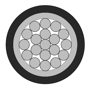
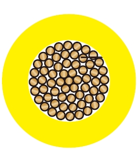
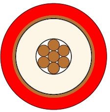
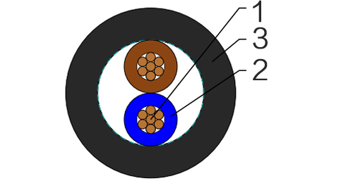
Conductor : Annealed copper conductor, solid or stranded according to BS EN 60228 class 1 or class 2.
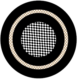
Insulation : XLPE type GP8 according to BS 7655-1.3. Crosslinked polyolefin material type EI 5 according to EN 50363-5 can be offered as option.
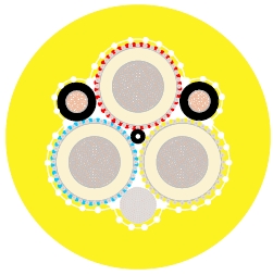
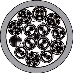
Inner Covering Option : The optional inner covering, where used, shall consist of an extruded layer of synthetic polymeric material. It shall surround the laid-up two, three, four or five cores, giving the assembly a practically circular shape.
Outer Sheath : Extruded LSZH type LTS 4 according to BS 7655-6.1.
Outer Sheath Option : UV resistance, hydrocarbon resistance, oil resistance, anti-rodent and anti-termite properties can be offered as option.
Insulation Colour :
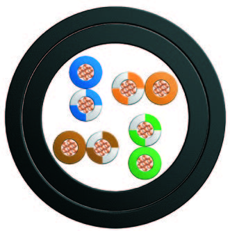
2-core : Brown and blue.
3-core : Brown, black and grey.
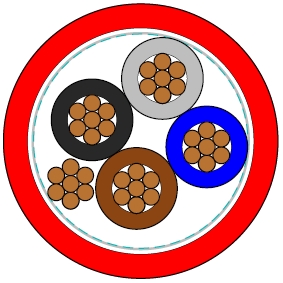
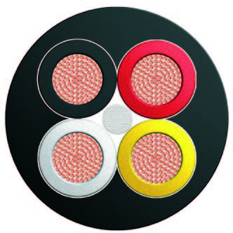
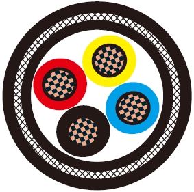
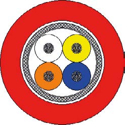
4-core : Blue, brown, black and grey.
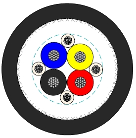
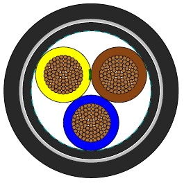
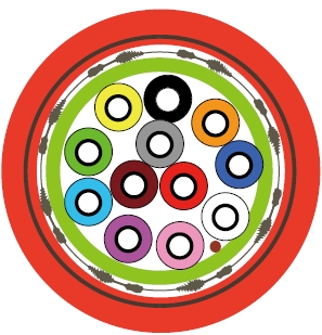
5-core : Green/yellow, blue, brown black and grey.
Sheath Colour : White; other colours can be offered upon request.
Maximum temperature range during operation : 90°C
Maximum short circuit temperature (5 Seconds) : 250°C
Minimum bending radius :
OD<8mm : 4 × Overall Diameter
8mm≤OD≤12mm : 5 × Overall Diameter
OD>12mm : 6 × Overall Diameter
| Conductor | FLP450-RZ1-U/R | ||||||
|---|---|---|---|---|---|---|---|
| No. of Cores × Cross-sectional Area | Conductor Class | Nominal Insulation Thickness | Nominal Inner Covering Thickness | Nominal Sheath Thickness | Min. Overall Diameter | Max. Overall Diameter | Approx. Weight |
| No.×mm² | mm | mm | mm | mm | mm | kg/km | |
| 2×1.0 | 1 | 0.7 | 0.4 | 1.2 | 7.1 | 9.5 | 94 |
| 2×1.5 | 1 | 0.7 | 0.4 | 1.2 | 7.6 | 10.1 | 121 |
| 2×2.5 | 1 | 0.7 | 0.4 | 1.2 | 8.4 | 11.0 | 165 |
| 2×4 | 1 | 0.7 | 0.4 | 1.2 | 9.2 | 12.1 | 212 |
| 2×6 | 1 | 0.7 | 0.4 | 1.2 | 10.2 | 13.2 | 272 |
| 2×10 | 1 | 0.7 | 0.4 | 1.4 | 12.1 | 16.0 | 446 |
| 2×1.0 | 2 | 0.7 | 0.4 | 1.2 | 7.3 | 9.7 | 110 |
| 2×1.5 | 2 | 0.7 | 0.4 | 1.2 | 7.8 | 10.3 | 132 |
| 2×2.5 | 2 | 0.7 | 0.4 | 1.2 | 8.5 | 11.3 | 178 |
| 2×4 | 2 | 0.7 | 0.4 | 1.2 | 9.5 | 12.4 | 232 |
| 2×6 | 2 | 0.7 | 0.4 | 1.2 | 10.6 | 13.7 | 302 |
| 2×10 | 2 | 0.7 | 0.6 | 1.4 | 12.7 | 16.7 | 490 |
| 2×16 | 2 | 0.7 | 0.6 | 1.4 | 14.4 | 18.8 | 674 |
| 2×25 | 2 | 0.9 | 0.8 | 1.4 | 17.7 | 23.2 | 1040 |
| 2×35 | 2 | 0.9 | 0.8 | 1.6 | 20.0 | 26.0 | 1130 |
| 3×1.0 | 1 | 0.7 | 0.4 | 1.2 | 7.5 | 10.0 | 110 |
| 3×1.5 | 1 | 0.7 | 0.4 | 1.2 | 8.0 | 10.6 | 143 |
| 3×2.5 | 1 | 0.7 | 0.4 | 1.2 | 8.8 | 11.6 | 198 |
| 3×4 | 1 | 0.7 | 0.4 | 1.2 | 9.8 | 12.7 | 260 |
| 3×6 | 1 | 0.7 | 0.4 | 1.2 | 11.2 | 14.4 | 387 |
| 3×10 | 1 | 0.7 | 0.6 | 1.4 | 12.8 | 16.9 | 557 |
| 3×1.0 | 2 | 0.7 | 0.4 | 1.2 | 7.7 | 10.2 | 128 |
| 3×1.5 | 2 | 0.7 | 0.4 | 1.2 | 8.2 | 10.9 | 156 |
| 3×2.5 | 2 | 0.7 | 0.4 | 1.2 | 9.0 | 11.9 | 213 |
| 3×4 | 2 | 0.7 | 0.4 | 1.2 | 10.1 | 13.1 | 282 |
| 3×6 | 2 | 0.7 | 0.4 | 1.4 | 11.6 | 15.0 | 387 |
| 3×10 | 2 | 0.7 | 0.6 | 1.4 | 13.5 | 17.7 | 607 |
| 3×16 | 2 | 0.7 | 0.6 | 1.4 | 15.3 | 19.9 | 850 |
| 3×25 | 2 | 0.9 | 0.8 | 1.4 | 18.9 | 24.6 | 1315 |
| 3×35 | 2 | 0.9 | 0.8 | 1.6 | 21.3 | 27.6 | 1562 |
| 4×1.0 | 1 | 0.7 | 0.4 | 1.2 | 8.1 | 10.7 | 130 |
| 4×1.5 | 1 | 0.7 | 0.4 | 1.2 | 8.7 | 11.4 | 170 |
| 4×2.5 | 1 | 0.7 | 0.4 | 1.2 | 9.6 | 12.6 | 240 |
| 4×4 | 1 | 0.7 | 0.4 | 1.2 | 10.7 | 13.8 | 330 |
| 4×6 | 1 | 0.7 | 0.4 | 1.4 | 12.2 | 16.1 | 445 |
| 4×10 | 1 | 0.7 | 0.6 | 1.4 | 14.1 | 18.4 | 687 |
| 4×1.0 | 2 | 0.7 | 0.4 | 1.2 | 8.3 | 11.0 | 150 |
| 4×1.5 | 2 | 0.7 | 0.4 | 1.2 | 8.9 | 11.7 | 185 |
| 4×2.5 | 2 | 0.7 | 0.4 | 1.2 | 9.9 | 12.8 | 256 |
| 4×4 | 2 | 0.7 | 0.4 | 1.2 | 11.0 | 14.2 | 344 |
| 4×6 | 2 | 0.7 | 0.6 | 1.4 | 12.7 | 16.7 | 490 |
| 4×10 | 2 | 0.7 | 0.6 | 1.4 | 14.8 | 19.2 | 747 |
| 4×16 | 2 | 0.7 | 0.6 | 1.4 | 16.9 | 21.8 | 1055 |
| 4×25 | 2 | 0.9 | 0.8 | 1.6 | 21.2 | 27.5 | 1670 |
| 4×35 | 2 | 0.9 | 1.0 | 1.6 | 23.5 | 30.7 | 2044 |
| 5×1.0 | 1 | 0.7 | 0.4 | 1.2 | 8.8 | 11.5 | 157 |
| 5×1.5 | 1 | 0.7 | 0.4 | 1.2 | 9.4 | 12.3 | 208 |
| 5×2.5 | 1 | 0.7 | 0.4 | 1.2 | 10.5 | 13.6 | 295 |
| 5×4 | 1 | 0.7 | 0.4 | 1.4 | 12.0 | 15.9 | 422 |
| 5×6 | 1 | 0.7 | 0.6 | 1.4 | 13.3 | 17.5 | 551 |
| 5×10 | 1 | 0.7 | 0.6 | 1.4 | 15.4 | 20.0 | 858 |
| 5×1.0 | 2 | 0.7 | 0.4 | 1.2 | 9.0 | 11.9 | 183 |
| 5×1.5 | 2 | 0.7 | 0.4 | 1.2 | 9.7 | 12.6 | 227 |
| 5×2.5 | 2 | 0.7 | 0.4 | 1.2 | 10.7 | 13.9 | 317 |
| 5×4 | 2 | 0.7 | 0.6 | 1.4 | 12.4 | 16.4 | 460 |
| 5×6 | 2 | 0.7 | 0.6 | 1.4 | 13.8 | 18.1 | 610 |
| 5×10 | 2 | 0.7 | 0.6 | 1.4 | 16.2 | 20.9 | 937 |
| 5×16 | 2 | 0.7 | 0.8 | 1.4 | 18.5 | 24.2 | 1328 |
| 5×25 | 2 | 0.9 | 1.0 | 1.6 | 23.3 | 30.5 | 1860 |
| 5×35 | 2 | 0.9 | 1.0 | 1.6 | 25.9 | 33.6 | 2500 |
Conductor operating temperature : 90°C
Ambient temperature : 30°C
| Conductor cross-sectional area | Ref. Method A (enclosed in conduit in thermally insulating wall etc.) | Ref. Method B (enclosed in conduit on a wall or in trunking etc.) | Ref. Method C (clipped direct) | Ref. Method E (in free air or on a perforated cable tray etc. horizontal or vertical) | ||||
|---|---|---|---|---|---|---|---|---|
| 1 two-core cable*, single-phase a.c. or d.c. | 1 three- or four-core cable*, three-phase a.c. | 1 two-core cable*, single-phase a.c. or d.c. | 1 three- or four-core cable*, three-phase a.c. | 1 two-core cable*, single-phase a.c. or d.c. | 1 three- or four-core cable*, three-phase a.c. | 1 two-core cable*, single-phase a.c. or d.c. | 1 three- or four-core cable*, three-phase a.c. | |
| 1 | 2 | 3 | 4 | 5 | 6 | 7 | 8 | 9 |
| mm² | A | A | A | A | A | A | A | A |
| 1.0 | 14.5 | 13 | 17 | 15 | 19 | 17 | 21 | 18 |
| 1.5 | 18.5 | 16.5 | 22 | 19.5 | 24 | 22 | 26 | 23 |
| 2.5 | 25 | 22 | 30 | 26 | 33 | 30 | 36 | 32 |
| 4 | 33 | 30 | 40 | 35 | 45 | 40 | 49 | 42 |
| 6 | 42 | 38 | 51 | 44 | 58 | 52 | 63 | 54 |
| 10 | 57 | 51 | 69 | 60 | 80 | 71 | 86 | 75 |
| 16 | 76 | 68 | 91 | 80 | 107 | 96 | 115 | 100 |
| 25 | 99 | 89 | 119 | 105 | 138 | 119 | 149 | 127 |
| 35 | 121 | 109 | 146 | 128 | 171 | 147 | 185 | 158 |
Note: With or without a protective conductor.
| Conductor cross-sectional area | Two-core cable, d.c. | Two-core cable, single-phase a.c. | Three- or four-core cable, three-phase a.c. | ||||
|---|---|---|---|---|---|---|---|
| 1 | 2 | 3 | 4 | ||||
| mm² | mV/A/m | mV/A/m | mV/A/m | ||||
| 1.0 | 46 | 46 | 40 | ||||
| 1.5 | 31 | 31 | 27 | ||||
| 2.5 | 19 | 19 | 16 | ||||
| 4 | 12 | 12 | 10 | ||||
| 6 | 7.9 | 7.9 | 6.8 | ||||
| 10 | 4.7 | 4.7 | 4.0 | ||||
| 16 | 2.9 | 2.9 | 2.5 | ||||
| r | x | z | r | x | z | ||
| 25 | 1.85 | 1.85 | 0.160 | 1.90 | 1.60 | 0.140 | 1.65 |
| 35 | 1.35 | 1.35 | 0.155 | 1.35 | 1.15 | 0.135 | 1.15 |
Note :
r = conductor resistance at operating temperature
x = reactance
z = impedance